 Air travel in the UK is on the rise again following a post-recession dip. In the first quarter of 2012 alone, almost 45 million passengers arrived in or departed the country aboard 420,000 flights. Yet when getting on a plane we rarely think about the intricate air-traffic control system keeping us safe in the sky.
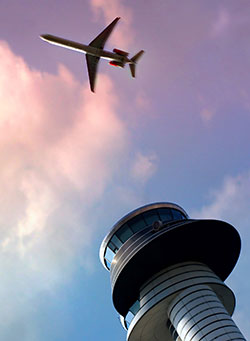
At any one time there are hundreds of aircraft flying above the UK. Safely choreographing their movement requires precise knowledge of the planes’ location, speed and direction of travel. This map of the skies is created by beaming radar signals skyward. Air Traffic Control radars may be divided into two classes, primary and secondary. In the case of primary surveillance radars (PSR’s), the energy reflected from aircraft can then be analysed to directly extract this information. In the case of secondary surveillance radars (SSR’s) the incident radar signals are first detected by a transponder aboard the aircraft. The transponders then send a message back in the direction of the radar signal, identifying themselves and giving key information about their plane’s movement. Using either system, air traffic controllers can then ask the pilot to adjust their course, maintaining a safe distance from neighbouring planes.
However, ground-based radar antennas need to be calibrated properly so that they perform accurately enough when trying to beam a signal to a small, moving target a considerable distance away. Technically, customers buying radar antennas are interested in the ratio between the main beam energy and side lobe energy. Side lobes are areas adjacent to the main beam where energy can leak into, decreasing the overall power of the main beam. Poor side lobe performance tends to decrease the sensitivity of radars to approaching aircraft, reducing the range at which they can operate and potentially leading to increased clutter on an air traffic controller’s radar screen.
In the decades after the Second World War, radar antennas were tested outside on a range. With the antenna placed on top of a tower at one end of a field, receivers were installed at the other end to measure the radar pattern at a large distance. This method, known as far-field measurement, has significant problems, however. Issues include inclement weather, radar signals bouncing off the ground and, more recently, interference from signals in the mobile phone and other frequency bands. Mathematics provides a better way to do it.
Modern radar testing facilities, like the one at BAE Systems’s Advanced Technology Centre, near Chelmsford, measure the radar pattern at much closer quarters and then mathematics is used to work out what that pattern would look like further away. By using mathematics, hundreds of millions of pounds worth of civil and military radar antennae a year can be tested more easily and accurately than ever before.
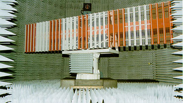 The testing facility consists of an anechoic chamber – a room designed to stop any echoes or reflections of the radar signals within the room. Unlike out on the far-field range, it is also prevents interference from external signals like mobile phones. This is achieved both by carefully engineering the size and shape of the room – the BAE Systems chamber is seventeen sided – and by lining the chamber with cones of an electrically resistive foam. The antenna is placed in the centre of the chamber and rotated. Detectors then measure the electric field in the immediate vicinity of the antenna which is why this technique is referred to as near-field.
From these measurements, a map of the electric field pattern on an imaginary sphere or cylinder close to the antenna can be constructed. This is done by solving Maxwell’s equations – a set of four equations laid down by 19th century Scottish physicist James Clerk Maxwell, often considered the father of modern electro-magnetics. At a further distance away, the energy contained within this near-field will become the radar pattern. To work out what this pattern would look like, and whether it is accurate enough to meet strict industry standards, an area of mathematics known as Fourier analysis is used. Named after French mathematician Joseph Fourier, the technique allows engineers to know what the electric field would look like at any other distance or place in space beyond the original imaginary sphere.
With the aviation industry contributing £18.4 billion a year to the UK economy and a further £14 billion brought in by the international passengers arriving in the country, the mathematics behind radar antenna calibration ensures the safety of aircraft in British skies.
Technical Supplement
Maxwell’s Equations
Maxwell’s equations are a set of four partial differential equations that relate the strength of electric and magnetics fields to currents and charges. As such they unify the Laws of Electrostatics, such as Gauss’s Law with the time dependent behaviour of moving charges described by Ampere’s and Faraday’s Laws, leading to a unified theory of electromagnetism. These equations, used together with vector calculus, are thus very powerful. They allow the prediction of the full range of static and time varying electric and magnetic phenomena, from the behaviour of radio waves to light, from light bulbs to electric motors and generators, and from linear accelerators to lightning. Wherever electric charges or magnetic poles exist, there will be a corresponding electric or magnetic field, and whenever charges accelerate, radiation is emitted. The design of near field antenna measurement ranges would not be possible without Maxwell’s Equations, where they are used to predict the behaviour of microwave radiation transmitted from the antenna under test and the electrical characteristics of the probe used to sample the signal, together with scattering and reflection effects from surfaces and other chamber structures.
Fourier Transforms
Fourier transforms are the workhorse of signal processing, and pop up in many other areas of science and engineering. In its basic form, a Fourier transform is computed by a simple, but potentially time-consuming summation – this summation is hugely accelerated when the Fast Fourier Transform algorithm is used in place of the simple summation. For the antenna testing case, slightly more esoteric transforms may be required, depending upon the geometry of the measurement setup. For data collected on a cylindrical surface, Fourier-Bessel transforms are required; for a spherical surface, transforms using spherical harmonics are the order of the day. There are fast algorithms for all these transforms.
References
Arthur D Yaghjian, “An overview of Near-Field Antenna Measurements”, IEEE Transactions on Antennas and Propagation, January 1986.
Printable Version
Download a printable version here:


