Doireann O’Kiely was awarded the IMA Lighthill-Thwaites Prize at the British Applied Mathematics Colloquium (BAMC), held at the University of Surrey in April, for her work on the production of thin glass sheets [1].
Thin glass sheets have many modern applications including touch-screens, cameras and thumbprint sensors for smartphones. Glass sheets with thicknesses in the range 50–100 μm are flexible, and this points to exciting future technologies such as bendable, rollable and even wearable tablet devices. For these devices to become a commercial reality, new techniques must be developed to enable the efficient and reliable manufacture of very thin glass sheets. Mathematical modelling provides a useful tool for improving these new manufacture processes.
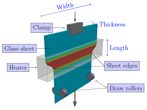
In the glass sheet redraw process, a prefabricated glass sheet is fed through a heater and stretched (see Figure 1). When the glass is hot it behaves as a viscous fluid. As the glass is stretched, it gets thinner and the edges of the sheet are pulled in. This combined response means that both the thickness and the width of the sheet decrease, and the cross-section of the sheet can change shape so that the final product may not have uniform thickness. The sheet segment shown in Figure 2 was produced by starting with a glass sheet with a uniform thickness of approximately 2 mm. The redrawn sheet is extremely thin (approximately 100 μm), except for a small region near the edge that is significantly thicker (approximately 500 μm).

This non-uniform thickness profile is problematic for two reasons. Firstly, the thick edges mean the sheet is less flexible, and more likely to break during post-production. Secondly, glass applications in optics and other technological devices must have very precise specifications, so parts of the sheet with varying thickness must be removed and discarded.
When using mathematical modelling to study the redraw process, the glass sheet is treated as a thin viscous sheet whose surfaces are free to move. The ultimate goal is to modify the process so that the redrawn sheet has uniform thickness, even at the edges. To address this problem, we must first understand why the thick edge forms.
As the sheet moves through the heater, its speed in that direction is increased by a factor D known as the ‘draw ratio’ and defined as the ratio between the final and initial speeds of the glass sheet. The volume of glass exiting the system must match the volume entering, so the increase in velocity must be balanced by a decrease in the width and/or thickness of the sheet.
We can describe the situation in more detail by considering the shape of the surface. The key is that the entire surface is free to move when the glass is molten, including the sheet edges (labelled in Figure 1). When the sheet edges move inward, glass is displaced. If the heater is sufficiently long compared to the sheet width, then the edges move a significant distance, but the displaced glass is gradually redistributed across the sheet. By contrast, if the heater is short so the glass is only molten for a short interval, then the sheet edge can only travel a short distance, and so the sheet thickness must decrease significantly to conserve volume. However, there is not enough time for glass to be redistributed from the displaced edge, and as a result the edge of the redrawn sheet is thicker than the rest of the sheet.
The latter scenario, in which a wide glass sheet is passed through a short heater, is of particular industrial interest because it can be used to produce desirable thin, wide sheets, and this motivates a mathematical study into the formation of thick edges. When the heater is short, the main portion of the sheet does not ‘feel’ the behaviour of the sheet edges.
Asymptotic analysis in the limit where the heater is short compared to the sheet width indicates that the behaviour in the main part of the sheet is one-dimensional – it varies only in the direction of motion – and there is a region near the sheet edge where the behaviour is two-dimensional and whose width is comparable to the heater length.
As a result, the glass far from the sheet edge behaves in a straightforward way: the thickness is required to decrease in proportion to the increase in the sheet speed, so
![\[\frac{final\ thickness}{initial\ thickness} = \frac{1}{D}.\]](https://ima.org.uk/wp/wp-content/ql-cache/quicklatex.com-8f4809b15ec9ac7469da25d1054335b3_l3.svg "Rendered by QuickLaTeX.com")
Near the sheet edge, the two-dimensional behaviour is best described using a numerical solution (see Figure 3). This numerical solution illustrates that, during redraw, the sheet gets thinner and the edge necks in. The glass in the path of the inward-moving edge accumulates, leading to the‘thick-edge’ phenomenon observed in Figure 2. Although this necking-in must be calculated numerically, analysis of the equations governing the fluid flow at the sheet edge show that the thickness of the edge itself is governed by
![\[\frac{final\ thickness}{initial\ thickness} = \frac{1}{\sqrt{D}}.\]](https://ima.org.uk/wp/wp-content/ql-cache/quicklatex.com-de6a239f17c7ab639cbefb3034092484_l3.svg "Rendered by QuickLaTeX.com")
The two different formulas for thickness at, and far from, the sheet edge quantify the discrepancy between the sheet edges and the main portion of the sheet. If the initial thickness at the edge is the same as elsewhere (i.e. if the sheet has uniform thickness), then the final thickness at the edge will be larger than elsewhere. By extension, these formulas suggest that if we modify the initial thickness appropriately, then we can produce a sheet with uniform final thickness.
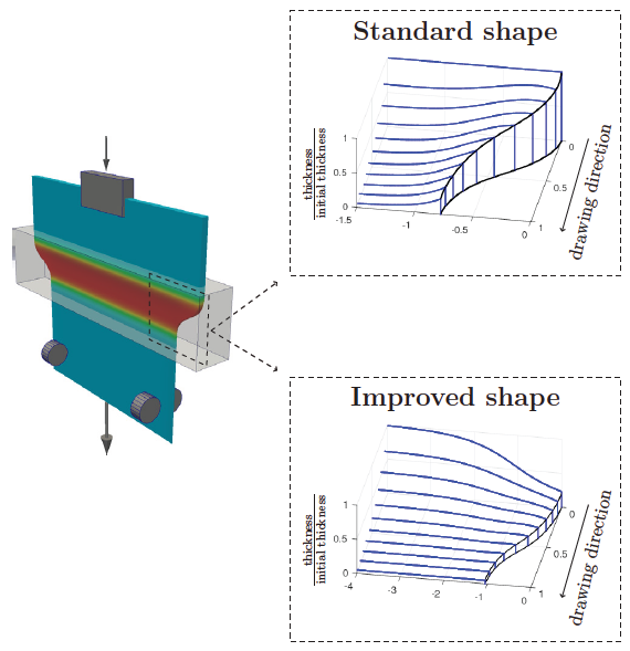
The same numerical scheme used to calculate the final thickness profile when a sheet with uniform initial thickness is redrawn can also be used to determine the modified shape required for the manufacture of a uniformly thin sheet. An example is shown in Figure 3 of a modified glass sheet which can be redrawn to a product with uniform thickness. Physically, a small region at the edge of the sheet is tapered, making it thinner to compensate for the accumulation of glass during redraw. The rest of the sheet, which is not shown here, does not need to be changed.
In summary, the mathematical model describing the glass sheet redraw process not only quantifies the edge-thickening phenomenon but also predicts a change to the initial shape that can be used to produce perfectly flat glass. This simple modification removes the danger of breakage introduced by thick edges, taking glass technology one step closer to flexible phones, bendable TVs and fashion-forward tablets.
Doireann O’Kiely
University of Oxford
Chris Breward FIMA
University of Oxford
Ian Griffiths
University of Oxford
Peter Howell
University of Oxford
Ulrich Lange
Schott AG
References
- O’Kiely, D., Breward, C.J.W., Griffiths, I.M., Howell, P.D. and Lange, U. (2015) Edge behaviour in the glass sheet redraw process, Journal of Fluid Mechanics, vol. 785, pp. 248-269.
Reproduced from Mathematics Today, June 2017
Download the article, Mathematics for Glass Manufacture (pdf)


