Reflecting on an encounter with the Bath, Wiltshire and North Devon Gliding Club during a pleasant afternoon’s walk around the Deverill valley, Alan Champneys ponders how aircraft actually stay in the air. This would seem a simple question, one whose answer is covered in A-level physics textbooks, and is drummed into successive cohorts of first-year undergraduate aerospace engineering students. Yet, digging a bit deeper, these simple explanations seem to differ widely. In each, many of the same words occur; Newton’s second law, Bernoulli’s principle, pressure differentials, boundary layers, vorticity, etc. Yet no single explanation really suffices, and some are just plain wrong. The real answer, as it often is, appears to be more subtle and gives us another glimpse at the complexity of fluid mechanics. This leads to an observation on the role of mathematical modelling both in aiding engineering design and in enabling simplified scientific explanations.
How the Deverill Do They Do That?
The Deverill valley is a curious spot, on the edge of the Cranborne Chase Area of Outstanding Natural Beauty, in a small pocket of Wiltshire that juts out into Somerset, close to its border with Dorset. Here is the last bastion of chalk downland, before the landscape is transformed into more familiar Jurassic landscapes to the West. There are five villages. Longbridge Deverill is on the main A350 from Shaftesbury to Warminster, but venture into the valley and you encounter the more remote Hill Deverill, Brixton Deverill, Monkton Deverill and Kingston Deverill. Many road signs simply point to ‘The Deverills’, the name thought to derive from ‘diving rill’ where the upper reaches of the River Wylye disappear and dive underground. There is an ethereal, timeless quality to the valley.
Archaeological evidence shows that the area has been farmed for more than 5000 years, and as with much of the downland in southern England, there are several prehistoric long barrows. Two Roman roads cross at Kingston Deverill. There are five separate churches in the villages, each of which can trace its origins to the 12th century if not before.
Starting out opposite Kingston Deverill church on a clear, late winter afternoon, my wife and I took the gently climbing path around the hill on the north side of the valley. We began to hear strange whirring noises, which we imagined to be some eerie bird scarer protecting some recently sown crop. After about a mile, as we rounded a bend, all became clear. We had encountered the Bath, Wiltshire and North Devon Gliding Club in full session; the periodic whirring being the noise of the winch used to tow the smaller gliders into the air. We stopped and watched.
Each flight began with the attachment of a tow rope. When the appropriate height is reached, the rope detaches from the glider, flies to earth on a little parachute and, once landed and presumably the winch’s motor disengaged, the end of the rope is brought back to the start of the landing strip by Land Rover, ready for the next flight. We were transfixed by the beauty of the gliders once they were set free from the rope into free flight. Near silent, they seem to defy gravity; circling over the low chalk hills, occasionally obscured from view, until each time being steered back to just the right height and position to land in the narrow field. From a distance, their motion seems more like that of a bird than an aeroplane. Presumably their long wing spans and light weights enable them to be manoeuvred at much lower airspeeds than passenger airliners.
This made me think again about something I had pondered for many years; how do aircraft fly? Doesn’t everyone know this? At the simplest level, it is about balance of forces. Four forces to be precise; gravity, thrust, lift and drag. Roughly speaking, the engine thrust (not present in gliders) is necessary to overcome the obvious fluid drag forces. Lift is then the property of the airflow over the wings and other control surfaces that provides an upward thrust to counteract gravity. Of course it is more subtle than that, and controlled changes to the angles of pitch, roll and yaw can allow these forces to work in other ways.
But, fundamentally, what causes lift? I recall the following explanation from my schooldays. Consider a simplified 2D cross-section and ignore any unsteady and out-of-plane (if you excuse the pun) effects; see Figure 1(a).
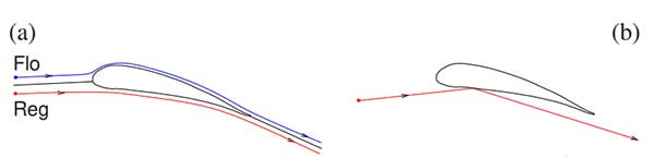
It is all about the flow regime around such a wing section. So let’s imagine two fluid particles, Flo and Reg say, sitting in the free air waiting for a plane wing to come along and disturb them. With most explanations of lift, it is better to consider a frame where the wing is stationary and Flo and Reg are moving towards the aircraft at a steady horizontal velocity. Flo is destined to be dragged over the aeroplane wing, whereas Reg will carry on undisturbed, beneath the wing. The special aerofoil shape of the wing means that Flo has further to go, she has to rise over the curved section of the aerofoil, before detaching from its trailing edge. In order to meet up with Reg again, thus avoiding a discontinuity in the flow, Flo has had to travel further. Therefore on average, Flo must travel faster than Reg.
Next we appeal to Bernoulli’s equation for conservation of energy along a streamline of steady flow, namely
(1) 
where  is the fluid velocity,
  its pressure,
  its density, and
  is altitude. Given that there is minimal change in altitude, and assuming the flow to be subsonic and
  const., we arrive at Bernoulli’s principle, that a rise in velocity must be accompanied by a drop in pressure. Thus, because Flo and all her friends going over the top are travelling faster than Reg and his mates, there must be a lower pressure above the wing than below it. This pressure difference leads to a net upwards force on the wing, namely lift.
As has been pointed out quite a few times over the years, see e.g. [1-6], there is a fundamental problem with this explanation. There is no principle in physics which dictates that, once separated, Flo and Reg should ever meet again. In fact, from the results of modern computational fluid dynamics (CFD), see Figure 2, and clever flow visualisation in wind tunnels, see Figure 3, we can see that Flo and Reg do not meet up. Rather, for an aerofoil that is generating lift, Flo gets to the back of the wing way before Reg. The flow over the longer route not only goes faster, it goes much faster than the simple explanation would suggest. But why?
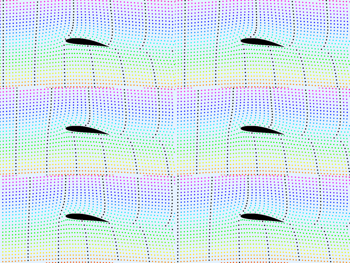
Figure 3: Wind-tunnel visualisation of flow over an aerofoil using pulsed smoke trails.2
NASA’s Glenn Research Center maintains an excellent educational website to explain aerodynamics to school students and lifelong learners [4]. It provides three basic ‘incorrect’ theories of lift, of which the above longer-path theory is number 1, before trying to give the truth. Explanation 2 is based not on Bernoulli’s principle but Newton’s third law. Accordingly, it is not Flo’s actions that cause lift, but it is Reg and his friends beneath the wing that do all the work. As the little air particles hit the underside of the wing, they bounce off, like ping-pong balls (Figure 1b). According to Newton’s law, this gain in downwards momentum of the air must be accompanied by an upwards change in momentum of the wing. Hence there is lift.
However it is fallacy to think of fluid particles like ping-pong balls. We know from everyday experience, e.g. with hairdryers, that fluid flows around obstructions rather than bouncing back. Also, if you look carefully at the computations in Figure 2, while it is undoubtedly true that on average, air is deflected downwards, the majority of the deflected air comes from above the wing (Flo) rather than below it (Reg).
The third NASA incorrect explanation is a variant of the first, relying on Bernoulli’s principle, but with a different explanation for the speed-up over the wing. This is supposed to occur due to a well-known principle arising from conservation of mass, that flow in a pipe speeds up if the diameter decreases. In effect, the upper surface of the wing and the straight streamlines in the far field above it, act like a Venturi tube which squeezes Flo and her mates into a narrower, faster flowing channel. Reg on the other hand remains in the slow lane. The fallacy here, as can be seen in Figures 2 and 3, is that there is no upper boundary of unperturbed streamlines above the wing. As Flo’s streamline is lifted over the wing, so are all the streamlines above her, albeit by a lesser amount.
Another popular ‘false’ explanation of lift is the so-called Coandă effect, which is the tendency of a fluid jet to stay attached to adjacent surfaces that curve away from the flow. This effect in reverse (the movement of the ball rather than the jet) is responsible for the popular demonstration in hands-on science museums of a beach ball being kept afloat by becoming entrained to the flow beside a vertical jet of air. So, if the angle of attack (angle of the wing’s chord to the oncoming flow field) is positive so that the trailing edge of the wing slopes downwards, then the Coandă effect gives downward momentum to Flo and friends. Thus we have a variant of the Newton’s third-law explanation, but now it is primarily Flo rather than Reg’s streamline that is bent downwards. The fallacy here is that the Coandă principle simply does not apply because the incoming flow is a uniform stream, not a jet.
In fact, rather than a fast flowing jet sticking to the upper surface, it is actually a thin boundary-layer of slower moving fluid. Nevertheless, that the boundary layer remains attached all the way to the trailing edge is a crucial ingredient for lift. Boundary-layer detachment due to either an excessive angle of attack, too little forward airspeed, or roughening of the wing’s surface due to icing, leads to the catastrophic loss of lift known as stall. But that is another story.
Finally, after several pages of incorrect explanation, the NASA website purports to give the true explanation of lift [4]:
The real details of how an object generates lift are very complex and do not lend themselves to simplification.
Newton’s laws of motion are statements concerning the conservation of momentum. Bernoulli’s equation is derived by considering conservation of energy. So both of these equations are satisfied in the generation of lift; both are correct. The conservation of mass introduces a lot of complexity into the analysis and understanding of aerodynamic problems.
While completely correct, this explanation smacks to me of the beyond the scope of the current investigation cop-out of which I, among many others, am frequently guilty.
The otherwise excellent Wikipedia article is, in my view, similarly opaque when it comes to the punch line [6]:
Sustaining the pressure difference that exerts the lift force on the airfoil surfaces requires sustaining a pattern of non-uniform pressure in a wide area around the airfoil. This requires maintaining pressure differences in both the vertical and horizontal directions, and thus requires both downward turning of the flow and changes in flow speed according to Bernoulli’s principle. The pressure differences and the changes in flow direction and speed sustain each other in a mutual interaction. The pressure differences follow naturally from Newton’s second law and from the fact that flow along the surface follows the predominantly downward-sloping contours of the airfoil. And the fact that the air has mass is crucial to the interaction.
So, both Newton and Bernoulli are necessary to understand lift. But what causes and sustains this symbiotic interaction between pressure differences and changes in flow direction? What turns it on? Could it be turned off?
In 2003 the Daily Telegraph reported that the question of what causes lift had finally been solved. The report was based on the popular article by Holger Babinski from the Engineering Department at Cambridge University [1], which included the beautifully illustrative wind-tunnel demonstration of streamlines in Figure 3. In providing the clearest yet experimental debunking of the longer-path theory, he also postulated a much simpler geometric explanation of lift. Differentiating the Bernoulli equation (1) in the normal direction, we find that curvature of a streamline leads to a pressure gradient. Positive (anticlockwise as the flow moves from left to right) change in curvature leads to an increase in pressure in an upwards direction. In looking at the flow field, there are a lot of positive curving streamlines above the wing, and far fewer below it. Given that ambient pressure is the same way above and way below the wing, this implies less pressure on the upper wing surface, and hence lift.
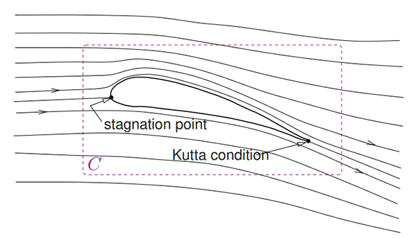
But, how can we calculate the amount of lift? Another explanation, and probably the one that is hinted at in the NASA article and to be fair to the Wikipedia page is included in a section on ‘Mathematical theories of lift’, relies on inviscid theory using the Euler equations under the approximation of irrotational (curl free) flow. Then the equations of fluid motion reduce to that of finding a complex potential, with the real and imaginary parts giving the horizontal and vertical components of the velocity field. The flow lines can then be solved quasi-analytically using complex variable theory if one makes an assumption (called the Kutta condition) that streamlines leave the trailing edge tangentially.
 .
.Then there is a nice result, the Kutta -Joukowski theorem. Consider a contour in the flow field that surrounds a solid body such as an aerofoil, so that near-wing viscous and boundary-layer effects can be ignored; see Figure 4. We define circulation to be the path integral
![\[\Gamma = \oint_C \mathbf{v} \cdot \mathrm{d} s,\]](https://ima.org.uk/wp/wp-content/ql-cache/quicklatex.com-3111e9905c3be86da2a40c7f99f274ba_l3.svg "Rendered by QuickLaTeX.com")
where  is the planar velocity field. Then the Kutta–Joukowski theorem states that there is resultant lift force on the body
(2) 
where  is the free-stream velocity in the far field. The proof of the Kutta-Joukowski theorem is relatively elementary, but beyond the scope of the current
In our example, in the aerofoil frame of reference, free-stream velocity is horizontal from left to right. Thus a negative (clockwise) circulation  gives rise to positive lift. According to the recent popular explanation [2], this prediction has both turned out to be quantitatively accurate, and also to give the ‘true’ explanation for lift. Lift occurs because the aerofoil introduces circulation.
Let me make a few observations. First, the theory is inviscid, but viscosity is crucial to understand the point of separation of the boundary layer, and so the theory cannot predict the loss of lift due to stall. Second, the theory is irrotational. Now, the eager-eyed reader might have spotted an apparent contradiction. From Stokes’ theorem, for a domain  surrounded by a closed curve ,
![\[\oint_C \mathbf{v} = \int \! \int_\Omega \operatorname{curl} \mathbf{v} \mathrm{d} x \mathrm{d} y.\]](https://ima.org.uk/wp/wp-content/ql-cache/quicklatex.com-ddc657932747d60103fb41ae3d25cf49_l3.svg "Rendered by QuickLaTeX.com")
But irrotational vector fields have zero curl, by definition. So how can we ever predict circulation using an irrotational theory? The resolution is that, in effect, the wing is equivalent to a point source of vorticity, or, in three dimensions, a line vortex. This equivalent vortex, should not be confused with general 3D effects such as wing tip vortices or the consequences of variation of lift along the wingspan, which are all beyond
Most seriously, I cannot help feeling that this ‘explanation’ of lift is somewhat circular (again, excuse the pun). The mathematics has enabled us to understand that differential flow above and below the wing causes circulation, which produces lift through the Joukowski–Kutta theorem. But from a physical point of view, we seem to be back where we started. What causes the differential flow speeds above and below the wing?
The University of Nottingham has produced a lovely series of videos, called Sixty Symbols, that try to explain the physics behind some well-known effects. In one such video, Michael Merrifield does one of the best jobs I have seen at explaining the causes of lift [5]. Like the NASA website, he says it is important to not just think of conservation of energy (the Bernoulli principle) or the conservation of momentum (Newton’s third law), but crucially to consider conservation of mass. He argues it is important to look in the vicinity of the stagnation point at the front of the aerofoil. Here the air bunches up. Streamlines get compressed. Conservation of mass (as in the Venturi-tube explanation) shows this bunched-up fluid must speed up as it passes over the wing. If the stagnation point is biased towards the bottom of the wing (as it is in a positive angle of attack) then there is more fluid acceleration over the top, hence lower pressure, hence lift.
Back in the Deverills, I could have gazed all afternoon at the gliders in flight. But, we needed to continue our walk. It soon became clear that our route would encroach the grass strip in which the gliders were parked at the end of their airstrip. I double checked the map. Were we off the path? And why was a somewhat official-looking man with clipboard and hi-vis jacket walking towards us?
I recalled a family walk a few years earlier on a public footpath on the other side of the Deverill valley. A ruddy-faced farmer had followed us in his tractor to tell us we had parked our car on private property, his private property. We hadn’t. It was a public road. Nevertheless he had insisted that I, the driver, take a ride back with him to move my car away from his farm. His attitude had appeared to me that, despite public rights of way, grockles3 were not welcome in his valley. Were we about to experience similar Deverill hospitality?
Not in the slightest! The charming club official invited us to come and watch from close quarters. He was keen to answer all our questions about how the gliders worked, whether they were privately owned, how long one needs to train to be a pilot, how the weather affects flights, whether it is an all-year-round sport. We were enthused.
Despite my thoughts that day and my subsequent musings, have I really learned anything about what causes lift? Perhaps, the true lesson is about the nature of physical or mathematical ‘explanations’. As an applied mathematician, there is no fundamental difference between a CFD simulation, a physical law, an approximate theory and a heuristic explanation. They are all mathematical models. As we already know, all models are wrong, but some models are better than others. But what do we mean by better?
Fluid mechanics is complicated, we already knew that, and perhaps our attempts to reduce an explanation of lift to simple rules of thumb are always going to be in vain. But such rules of thumb are also mathematical models in a sense; they are heuristic models, whose purpose is to enhance understanding. The yardstick I would therefore propose for assessing different explanations of lift, or indeed any mathematical model, is not whether it is correct in any absolute sense, but whether it is useful.
Providing simple explanations which give the ability to generalise is an important use of mathematical models. Another use is for practical engineering purposes; to design, build, exploit, improve, and, increasingly, to replace expensive laboratory tests. To these ends, I like the pragmatism in the popular explanation by practising aerospace engineer and pilot Charles Eastlake [3]:
Two things are happening simultaneously as an airfoil produces lift. If we take the flow-field detail perspective, we use the conservation of mass and conservation of energy, Bernoulli’s law, to describe a streamline-squeezing pattern
Alan Champneys CMath FIMA
University of Bristol
Notes
- From [6] by Kraaiennest — Own work, CC BY-SA 3.0, tinyurl.com/CFD-simulation.
- Originally from [1], available at https://www.youtube.com/watch?v=6UlsArvbTeo.
- A derogatory West Country word for tourists.
References
- Babinski, H. (2003) How do wings work? Phys. Educ., vol. 38, pp. 497–503.
- Deshpande, M.D. and Sivapragasam, M. (2017) How do wings generate lift? Resonance, vol. 22, no. 1, pp. 61–77.
- Eastlake, C. (2002) An aerodynamicist’s view of lift, Bernoulli and Newton, Phys. Teach., vol. 40, pp. 166–173.
- Hall, N. ed. (2002–18) Theories of lift, Beginners Guide to Aeronautics, NASA Glen Research Center, www.grc.nasa.gov/www/K-12/airplane/wrong1.html (accessed 14 August 2018).
- Merrifield, M., McPartlan, P. and Haran, B. (2017) Lift and Wings, Sixty Symbols, The University of Nottingham, www.sixtysymbols.com/videos/lift_wings.htm (accessed 14 August 2018).
- Wikipedia, Lift (force), https://en.wikipedia.org/wiki/Lift_(force) (accessed 14 August 2018).
Reproduced from Mathematics Today, October 2018
Download the article, Westward Ho! Musing on Mathematics and Mechanics (pdf)